
Energy Management System EMS
The Real Core of Energy Storage Systems: The Ultimate Criterion for Judging Their Quality
It is responsible for coordinating energy flow, equipment operation, environmental control, and safety protection to ensure safe, efficient, and stable system operation.

What Does an Energy Management System (EMS) Do?
EMS acts as the command center for energy flow and performs real-time dispatch across these dimensions:
Multi-Scenario Operation and Intelligent Mode Switching
To support diverse application requirements, EMS supports flexible operating scenarios:
Predefined Operating Scenarios as :
- Peak shaving and valley filling
- Emergency backup power supply
- Grid-balancing
Each scenario is associated with a dedicated energy management strategy.
- Automatic and Manual Switching
- Manual one-click switching by operators
- Automatic switching triggered by predefined conditions
Example:
Automatic switch to emergency backup mode when grid disconnection is detected
Automatic activation of peak shaving during grid peak hours
User-Defined Strategy Expansion
EMS allows users to configure custom operating programs, enabling adaptation to complex and evolving application scenarios.
Energy Quantity Regulation
EMS regulates the amount of energy exchanged within the system based on application-specific dispatch strategies and multiple real-time constraints.The dispatch quantity is determined by a combination of the following factors:
- Grid dispatch instructions, including export/import commands and grid support requirements
- Real-time load variations, reflecting on-site power demand changes
- Grid or transformer capacity limits, which define the maximum allowable power exchange
- Battery operating status, such as state of charge (SOC), available power, and protection limits
- Real-time renewable generation output, such as photovoltaic or wind power production
By continuously evaluating these factors, EMS dynamically adjusts charging, discharging, and power exchange levels to ensure safe, compliant, and economically optimized system operation under the selected application scenario.
Energy Direction Control
An Energy Management System (EMS) controls how energy flows within a power system by coordinating both energy sources and energy destinations.Energy sources may include renewable generation, power imported from the utility grid, or battery discharge. Energy destinations may include charging the battery, supplying on-site loads, or exporting power to the grid.Energy dispatch decisions are determined by application-specific strategies and economic objectives, such as revenue maximization, reliability assurance, renewable energy utilization, and regulatory compliance, rather than energy efficiency alone.
Environmental and Auxiliary System Management
EMS provides centralized management of the power station’s operating environment and auxiliary equipment:
- Real-time monitoring of environmental parameters such as temperature, humidity, and dust concentration
- Supervision of auxiliary systems including ventilation, cooling, and lighting
- Automatic environmental control based on equipment operating conditions
Multi-Device Communication and System Integration
Battery System (BMS Interface)
Acquires real-time battery data such as SOC, SOH, voltage, and current
Issues charge and discharge commands based on battery status
Power Conversion System (PCS)
Controls PCS start/stop and operating modes
Adjusts AC/DC power conversion according to system demand
Electric Energy Meters
Collects real-time data on power consumption, generation, and grid export
Provides data for energy settlement and dispatch optimization
Utility Grid Interface
Exchanges data with the grid dispatch center
Receives grid instructions and reports system operating status
Ensures compliant and safe grid connection
Emergency Protection and Fire Control (BMS Failure Backup)
To mitigate risks caused by BMS failure, EMS includes a multi-layer emergency protection mechanism:
BMS Failure Detection
EMS continuously monitors:
BMS communication status
Data validity and consistency
Any abnormal condition is immediately identified as a failure and triggers alarms.
Emergency Energy Isolation
If the BMS fails to perform battery protection:
EMS takes over protection control
Immediately disconnects the battery from PCS or grid
Prevents overcharge, over-discharge, overcurrent, and thermal runaway
Fire Control System Linkage
EMS integrates with the fire alarm and fire suppression systems:
Triggers alarms when battery temperature exceeds safety thresholds
Activates fire extinguishing systems in battery compartments
Cuts off energy supply to affected areas to limit fire spread
Human-Machine Interface (HMI) and Local Operation
EMS typically includes a local Human-Machine Interface (HMI) deployed at the power station level, providing operators with real-time visibility and direct interaction with the system. Through the HMI, users can monitor operating status of the battery system, PCS, grid connection, loads, and auxiliary equipment, as well as view alarms, events, and key parameters under authorized access.
Data Storage, Cloud Connectivity, and Remote Visualization
MS continuously collects operational and environmental data from all connected devices, including power and energy data, battery SOC and SOH, alarms, events, and auxiliary system status. This data is stored locally to support event tracing, fault analysis, performance evaluation, and compliance reporting, ensuring data availability even during network interruptions.
At the same time, EMS supports secure data transmission to cloud platforms or remote servers, enabling remote monitoring and visualization via web portals or mobile applications. Cloud-based functions may include historical data analysis, alarm notification, maintenance support, and centralized management of multiple sites, allowing operators and asset owners to access system information without on-site presence.
Key Benchmarks for Evaluating EMS Excellence
What Defines a Truly Excellent EMS: Benchmarks Beyond Basic Functions
Response Speed (Real-Time Responsiveness)
This is often the top priority for grid services like frequency regulation and ancillary markets. A superior EMS must detect grid signals and execute charge/discharge commands in milliseconds to seconds, enabling seamless integration with dynamic grid demands. This includes accounting for the full response chain: from meter detection and data transmission to the EMS, to issuing power commands to the Power Conversion System (PCS), and finally the PCS’s ramp-up time (e.g., from 0-100% or even -100%-100% power). Key considerations also include refresh rates—meters and PCS typically refresh every 100ms, so EMS communication times with these components exceeding 200ms render the system ineffective for real-time control. In ideal scenarios, the entire process should complete within 500ms to meet stringent requirements.
Why critical:
Response speed is the foundational metric for services like Frequency Containment Reserve (FCR), where delays can lead to test failures or even penalties for non-compliance. It is equally vital in demand-side management (DSM), where slow EMS reactions can cause exceedances of grid capacity limits during sudden load spikes, risking operational inefficiencies or violations. Fast response enables participation in high-value services (e.g., FCR) while maintaining grid stability during fluctuations.
Adaptability (Flexibility Across Functions and Scenarios)
An excellent EMS must seamlessly switch between diverse applications—such as peak shaving, energy arbitrage, demand response, renewable integration, Frequency Containment Reserve (FCR), virtual power plants, and operation with multi-vendor hardware—while dynamically adapting to varying grid demands, market signals, regulatory requirements, and forecasts.
Why critical:
Energy storage projects rarely rely on a single use case. Rigid EMS designs severely limit revenue stacking (simultaneously participating in multiple value streams) and reduce future-proofing against evolving grid needs. In today’s most profitable operating models, customers increasingly require the EMS to automatically apply multiple scenarios across different time periods—for example, performing energy arbitrage during off-peak hours, providing FCR during high-frequency volatility periods, shifting to peak shaving in the evening, and supporting demand response when called by the grid operator—all without manual intervention. A highly adaptable EMS maximizes total revenue, extends asset lifespan through optimized operation, and ensures long-term competitiveness in rapidly changing energy markets.
Stability and Reliability
The EMS must operate consistently without crashes, communication failures, or downtime—even under extreme environmental and operational conditions, including high/low temperatures, humidity fluctuations, dust exposure, and potential cyberattacks.
Why critical:
Instability directly translates to lost revenue (missed market opportunities or grid service dispatches), heightened safety risks (e.g., uncontrolled battery behavior), and prolonged system unavailability. In real-world deployments, BESS containers are typically placed outdoors, where the internal cabinet environment can be extremely harsh—summer temperatures often exceed 60–70°C, while winter conditions can drop below -30°C, compounded by rapid thermal cycling, condensation, and dust ingress. Standard unprotected circuit boards or consumer-grade hardware used in many “budget” EMS solutions quickly degrade or fail under such stress, leading to frequent reboots, communication dropouts, or complete shutdowns. A truly reliable EMS, by contrast, employs industrial-grade components, robust thermal management, conformal coating, wide-temperature-rated electronics, and hardened cybersecurity measures. This ensures continuous, stable operation throughout the project lifecycle, minimizes unplanned maintenance, protects revenue streams, and meets the stringent availability requirements demanded by grid operators and investors.
Troubleshooting Capability (Diagnostic and Self-Healing Capabilities)
A superior EMS must possess strong troubleshooting and diagnostic capabilities, enabling rapid identification, isolation, and resolution of faults across the entire system—spanning batteries, PCS, meters, communication networks, and external interfaces—while minimizing downtime and manual intervention.
Why critical:
In large-scale or remote BESS deployments, faults (e.g., communication interruptions, sensor drift, PCS anomalies, or early battery degradation) are inevitable. Weak troubleshooting leads to prolonged outages, missed revenue opportunities, delayed maintenance, and higher operational costs. Traditional approaches rely on on-site connection of a laptop or upper computer to the BMS or PCS for diagnostics—a process that is time-consuming, costly, and impossible to perform remotely, especially since most BMS and PCS lack built-in Human-Machine Interfaces (HMI). An advanced EMS overcomes this limitation by effectively serving as a remote HMI surrogate for both BMS and PCS, allowing operators to access detailed diagnostics, view real-time parameters, retrieve fault logs, and perform root-cause analysis from anywhere via the EMS interface. Combined with automated real-time detection, precise fault coding, root-cause analysis, and self-healing actions (e.g., switching to redundant communication paths or bypassing faulty components), this capability dramatically improves system availability, reduces on-site service visits, lowers O&M costs, and enhances overall project bankability for investors and operators.
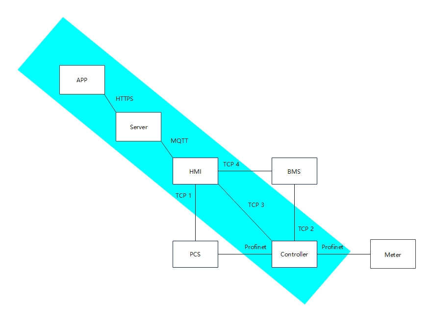
FFD POWER Ultra Fast EMS solution
FFD Power EMS (for BESS) integrates remote monitoring, cloud services, and on-site control via 4 core components (APP, Server, HMI, Controller). It features high real-time responsiveness, one-EMS multi-scenario adaptability, high stability/reliability, and full-range remote troubleshooting.
High real-time responsiveness
All scenario adaptability
High stability/reliability
Full-range remote troubleshooting
